WiFi that survives plaster, wire lath and four hundred neighboring networks
New York is close to the worst radio environment in the country: masonry that stops 5 GHz, wire lath that behaves like a screen, and a 2.4 GHz band with somebody else’s router in every direction. The fix is placement and cable, not a bigger box.
The building is the problem, and it is worse than you think
Radio behaves in ways that are easy to state and easy to forget. Higher frequencies carry more data and travel less far: at the same distance, 5 GHz starts about 6 to 7 dB down on 2.4 GHz from frequency alone, before it has hit anything. Then it hits things.
A modern interior partition costs 5 GHz a few decibels. A solid brick or masonry wall commonly costs somewhere between 6 and 18 dB. Reinforced concrete can cost 15 to 30 dB and effectively ends the conversation. And the specifically New York problem, the one that surprises people who have deployed wireless successfully everywhere else, is that a great deal of pre-war plaster in this city is applied over metal lath. That is a steel mesh inside the wall. It does not attenuate the signal so much as reflect it, and a room bounded by lath partitions behaves like a partially closed screen. It is why an access point that covers a whole floor in a 1990s office building covers two rooms in a 1910 apartment.
Add terra-cotta block partitions, tin ceilings, elevator shafts and stair cores that are essentially solid, foil-backed insulation in renovated units, and low-emissivity window coating that reflects signal back into the room, and the honest summary is that in a pre-war New York building, coverage is decided by where you can get cable to, not by which access point you buy.
The spectrum situation compounds it. The 2.4 GHz band has exactly three non-overlapping 20 MHz channels in the US (1, 6 and 11) and in a dense residential block every one of them is occupied by dozens of neighboring networks you cannot control, plus microwaves, older cordless phones and Bluetooth. You are not competing for coverage. You are competing for airtime.
Why a mesh extender is not a substitute for a cable run
Mesh is a genuinely useful technology used correctly and a very expensive way to be disappointed used as a shortcut. Here is the physics.
- A repeater spends its airtime twice. A node that talks to your laptop and to the upstream access point on the same radio has to receive the frame and then send it again on the same channel. That roughly halves usable throughput per hop. Two hops leaves you around a quarter. Adding a third node to fix a weak corner often makes the whole network slower, which is why mesh systems frequently get worse as people add units.
- Dedicated backhaul helps and does not solve it. Tri-band units reserve a radio for the link between nodes, which removes the halving, but that backhaul radio still has to get through the same wall that stopped the client signal. A mesh node placed where it has good coverage has a weak backhaul; placed where it has a strong backhaul it does not reach the room you bought it for. In a lath-and-plaster building that trade is usually unwinnable.
- Wired backhaul makes mesh work properly. Every serious deployment we build is access points on cable, coordinated as one system, with mesh available as a fallback for the one position where cable genuinely cannot go: a detached garage, a landmarked facade, a tenant space we are not allowed to open. That is the right use of it.
- A cable run is usually cheaper than the third extender. An additional Cat6 drop in commercial space typically runs $150 to $400 installed, terminated and tested, subject to survey. Three consumer mesh nodes cost about the same and deliver a fraction of the result. The drop also still works in ten years when the access point on the end of it is obsolete.
- Never put cameras or door hardware on wireless. A camera stream is a constant upstream load and a reader is a life-safety-adjacent path; both belong on copper. Wireless links for those exist and they are for the specific case where cable is genuinely impossible, not for saving a day of labor.
What each band is good for in a New York building
| Band | Range and penetration | Channel space | Where we use it |
|---|---|---|---|
| 2.4 GHz | The best penetration of the three, and the only one that reliably gets through a masonry wall or down a stairwell. | Three non-overlapping 20 MHz channels in the US, all of them full of your neighbors. | Kept on, at reduced power, for range-critical and low-bandwidth devices: sensors, older equipment, printers, building systems. Not for anything that needs throughput. |
| 5 GHz | Roughly 6 to 7 dB down on 2.4 GHz from frequency alone, and considerably worse through masonry, lath and concrete. | Many more channels, but a large block of them are DFS channels that must vacate on radar detection, a real event near the harbor and the airports, which shows up to users as everything dropping at once. | The workhorse band for laptops, phones and streaming. Most of a good design is 5 GHz cells that are deliberately small. |
| 6 GHz (Wi-Fi 6E and 7) | Shortest range of the three. It does not penetrate better than 5 GHz. It penetrates worse, and indoor operation is normally at reduced power. | By far the most spectrum, and almost none of it congested yet because there are no legacy devices in it. | Excellent in open, high-density spaces (a conference floor, a lobby, an open-plan office) where you can put an access point in the same room as the users. Poor at reaching through a pre-war wall, and no substitute for an extra AP. |
The counter-intuitive one: wider channels are not automatically better. An 80 or 160 MHz channel raises peak throughput for a single client but reduces the number of non-overlapping channels available, and spreads the same transmit power across more spectrum. In a dense building, 40 MHz channels on 5 GHz routinely deliver better real-world results for everyone than 160 MHz does for one person.
Count access points by clients and walls, never by square feet
The figure on the box (covers up to 2,500 square feet) is measured in an environment nothing in this city resembles. Two questions actually set the count.
How many devices are active at once, and what are they doing? Every device on a channel shares airtime with every other device on that channel, and a single slow client transacting at a low data rate consumes airtime out of all proportion to the data it moves. In a mixed office we plan around a working figure of roughly 25 to 30 concurrently active devices per radio; in a space where everyone is on video calls, fewer. A conference room for forty people is a capacity problem, not a coverage problem, and no amount of transmit power fixes it. The answer is another access point with a smaller cell.
What is between the access point and the user? One AP per two or three rooms in a lath-partitioned pre-war building is normal, and it is not because the equipment is weak. Turning transmit power up to compensate is the classic mistake: the access point shouts further, the client’s much smaller antenna and lower power cannot shout back, and you build a large cell full of devices that can hear the AP and cannot be heard. Good design uses more access points at lower power with deliberately small cells.
Placement, and the four places APs get put wrongly
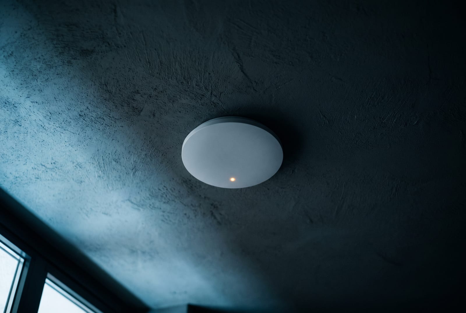
Access points belong in the open space they serve, mounted on the ceiling or high on a wall, radiating down and out. The four places we routinely find them, all wrong: above a suspended ceiling tile, where the tile, the grid and everything in the plenum sit between the antenna and the users; inside a metal enclosure or an IDF cabinet; in a corridor on the assumption that signal will turn into rooms, which it does poorly through a fire door; and in a corner of the building, where half the coverage pattern is radiating out over the street to nobody.
Roaming
A device that will not let go of a distant access point while standing next to a strong one is the most common complaint after a multi-AP install, and it is not really the network’s fault: the client decides when to move. What a properly configured system does is make the decision easy: neighbor reports and transition management so the client is told what else is available and steered, fast transition so the handoff is quick enough that a call does not break, matched network names and security settings across every AP, and disabling the very lowest legacy data rates so a distant client is not rewarded for hanging on. Getting this right is configuration work, and it is the difference between a system that tests well and a system people stop complaining about.
Power and uplink, which is where the cabling decision comes back
A current tri-band access point is not an 802.3af device. Many need 802.3at PoE+ at 25.5 W and some of the higher-end units want 802.3bt Type 3. Given only 802.3af, most modern APs will still boot, and then quietly disable a radio, drop to a lower power level, or shut off a secondary port. The symptom is a network that works but is inexplicably slow in one area, and the cause is a switch bought on port count. As with cameras, the switch’s total power budget is not its port count multiplied by its port rating, and it needs sizing with 15 to 20 percent headroom against actual draw.
Uplink speed matters now in a way it did not five years ago. A tri-band Wi-Fi 6E or Wi-Fi 7 access point can aggregate more than 1 Gbps across its radios, which means a gigabit uplink becomes the bottleneck in exactly the busy spaces where you deployed it. That points to multi-gig switch ports and Cat6A to the AP position, the one place in most buildings where Cat6A is genuinely worth the difference rather than being an upsell.
And the 100 m channel limit applies here as it does everywhere: 90 m of horizontal cable plus 10 m of patch cords, measured along the route the cable actually takes. Access points tend to end up at the far corners of a floor plate, which is precisely where that limit is reached, so on large floors the answer is often a second small closet with a fiber leg back to the main room rather than one heroic cable run. This is all covered in more depth on our structured cabling page, and it is the reason we would rather quote the wireless and the cabling together than inherit somebody else’s drops.
Apartment buildings: what actually works, and what boards keep being sold
The proposal a co-op or condo board is usually shown is building-wide resident WiFi from access points in the corridors. In a pre-war building it does not work, and the reason is structural rather than technical: the signal has to cross the corridor wall, the apartment entry door and then the unit’s own interior partitions, all of which are the masonry, lath and terra-cotta described above. Residents in the front rooms get nothing, and every unit still has its own router competing for the same three 2.4 GHz channels, so the building network makes the interference worse for everyone.
What works is one of two things. Genuine per-unit coverage means a cable drop and an access point inside each apartment, coordinated centrally: a real project with a real riser scope and a real budget, and worth doing only where the building intends to offer internet as a service. Or amenity coverage: strong, properly designed wireless in the lobby, laundry, gym, roof deck, package room, community room and garage, which is what most boards actually want when you ask them what problem they are solving, and which costs a fraction of the first option.
One more thing to settle before anything is ordered: building systems do not go on the guest network. Cameras, access control, intercom, elevator and BMS traffic belong on their own segments, isolated from resident and guest traffic, with rules that let them reach only what they need. A single flat network shared by residents and the door system is the most common serious security defect we find in New York multifamily buildings.
Predict, then measure, then measure again
Predictive design first. Floor plans get modeled with the actual wall materials, and in a New York building that means asking whether the plaster is over wood lath or wire lath, because the two produce very different answers. That gives an access point count and provisional positions to argue about before anybody buys anything.
Then a site survey with instruments. We walk the building and measure what is really there: existing signal levels, the neighboring networks on every channel, the noise floor, and how much a specific wall in your specific building actually costs. This is where predictions get corrected, and in older buildings they usually do get corrected.
Then install, tune and validate. Access points on cable, channels and power set as a plan rather than left on automatic, wider channels only where the spectrum can carry them, low legacy rates disabled, and roaming configured. Afterwards we walk the whole coverage area again with a survey tool and hand you the results: signal, noise, data rate and roaming behavior, room by room. If a corner does not meet the design target, we would rather find it with a laptop in our hands than in an email from a tenant.
You get the survey output, the channel and power plan, the access point positions on a drawing, and administrative credentials in your name. As with everything else we install, if you replace us, you should be able to.
Common questions
How many access points do we actually need?
It depends on walls and on how many devices are active at once, and never on square footage. The coverage figure on a box is measured in a space with almost nothing in it. In an open modern office, one access point per 2,000 to 3,000 square feet is a reasonable starting point. In a pre-war building with plaster over wire lath, it can be one per two or three rooms, because the walls behave like partial screens rather than like drywall.
Density changes the answer independently of coverage. Forty people in a conference room all on video is a capacity problem: every device shares airtime on the same channel, so the fix is another access point with a deliberately small cell, not more power on the existing one. We give a number after a predictive model and a walk with a meter, and the number after the walk is the one that goes on the quote.
Can we just use a mesh system instead? It is much cheaper.
For a two-bedroom apartment with drywall partitions, mesh is often genuinely fine and we will tell you so. For anything larger or older, the arithmetic works against it. A repeater that talks to your device and to the upstream node on the same radio has to send every frame twice, which roughly halves throughput per hop; two hops leaves about a quarter. Tri-band units with a dedicated backhaul radio avoid the halving, but that radio still has to cross the same wall that blocked the client signal in the first place.
The practical result in a lath-and-plaster building is that the node either sits where it has good coverage and a weak uplink, or where it has a good uplink and does not reach the room you bought it for. Meanwhile a Cat6 drop typically runs $150 to $400 installed, terminated and tested, subject to survey (roughly what three consumer mesh units cost) and it still works in ten years when the access point on the end of it is obsolete. We do use mesh, deliberately, for the one position where cable genuinely cannot go.
Why is 5 GHz slower than 2.4 GHz in some of our rooms?
Because it is behind more wall than it can afford. At the same distance, 5 GHz is already about 6 to 7 dB down on 2.4 GHz purely from frequency, and it loses far more crossing masonry, terra-cotta or metal lath. In the room next to the access point, 5 GHz will be much faster. Two lath walls away, 2.4 GHz gets through and 5 GHz does not, so the device falls back and appears slower.
The instinct is to raise transmit power, and that makes it worse in a way that is hard to see. The access point can now be heard further away, but your phone has a small antenna and much less power, so it cannot answer from where it now sits. You get a large cell full of devices with one-way audibility, all consuming airtime at very low data rates and slowing down everybody else. The real fix is another access point closer to the problem room, at lower power, on a different channel. Almost every “we need a stronger router” conversation ends there.
There is Cat5e in the ceiling already. Can you feed the access points with it?
Often, yes, and we will test rather than assume. Cat5e carries a gigabit to the full 100 m channel and will carry PoE+ to an access point that needs 25.5 W. If the runs test clean and are the right length, reusing them saves the most expensive part of the job.
Two things push us the other way. First, uplink speed: a current tri-band access point can move more than 1 Gbps across its radios in a busy space, so a gigabit uplink becomes the constraint exactly where you needed the capacity. That argues for Cat6A and a multi-gig switch port at those positions. Second, power: if a unit wants 802.3bt, high-power PoE in a dense bundle is a heat question, and larger conductors handle it better. Our normal recommendation is to reuse existing Cat5e for the ordinary positions and pull new Cat6A to the two or three access points that carry the load.
Can one system cover the whole apartment building from the hallways?
Almost never, in a pre-war building. Corridor access points have to get through the corridor wall, then a solid apartment entry door, then the unit’s own partitions. Residents at the front of a unit get nothing usable, and because every apartment still runs its own router on the same three crowded 2.4 GHz channels, the building system tends to add interference rather than replace it.
The two designs that do work are per-unit coverage (a cable drop and an access point inside each apartment, centrally managed, which is a genuine riser project with a genuine budget and makes sense mainly where the building intends to provide internet as a service) or amenity coverage, meaning properly engineered wireless in the lobby, laundry, gym, roof deck, package room, community room and garage. When we ask boards what problem they are actually trying to solve, amenity coverage is the answer about nine times in ten, and it costs a small fraction of the alternative.
Should the cameras, door readers and WiFi share one network?
They can share the physical cabling and switches. They should not share a network segment. Building systems belong on their own segments with rules that let each one reach only what it needs: cameras to the recorder and a time source and nothing else, no route out to the internet at all; access control to its controller and its management platform; guest wireless isolated from every one of them and from your own devices. And nothing production sits on the default VLAN, because that is the first place anybody looks.
The reason is not theoretical. Cameras and building controllers are among the most-exploited categories of connected device, they often run firmware that lags badly, and a flat network means anything that reaches the guest WiFi also reaches the door system. Segmenting it is a configuration decision made at design time and costs essentially nothing; retrofitting it after a building has run flat for five years is a project. This is one of the reasons we prefer to do the wireless, the cabling and the security systems as one scope rather than inheriting three vendors’ assumptions.
Work that usually comes with this
Structured Cabling
Cat6/6A and fibre backbones, racks, patch panels, certified and labelled.
Security Camera Installation
New IP camera systems for buildings, storefronts, offices and homes.
Access Control Installation
Complete door-control systems, from a single door to a multi-building portfolio.
Mobile & Cloud Access Control
Phone-as-credential systems with browser-based administration and remote unlock.
Low Voltage & Cabling
The Cat6, fibre, risers, racks and wireless that everything else depends on.
Tell us where the signal dies.
Send a floor plan and the rooms that do not work. We’ll model it, walk it with a meter, and come back with an access point count, positions and a price, not a bigger router.
Sun to Thu 9am to 5pm · Fri 9am to 12pm · Sat closed